Snes Usb Controller For Mac

First instructable. Let me know what it needs and fixes. I did not make the circuit or program. I am just making a guide that shows step by step assembly of how to make the USB SNES controller.
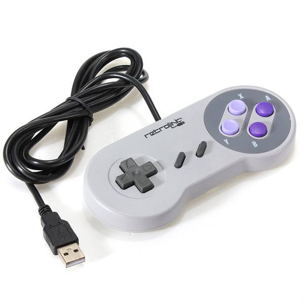
Features: For super nintendo SNES USB Controller for PC for MAC Controllers. Play your computer games with an old-school / Retro-feel! This USB controller allows you to play your favorite PC games by just plugging in your USB control! Just Plug n' Play no extra drivers needed!
Tr888 25/5/2010, 17:06 น. That's why you see warning about wrong certificate - server sends to the browser certificate for SSL communication. > What I don't understand --and this may be better asked somewhere else-- is > why YouTube/Google would not accept the connection Your assumption here is incorrect. YouTube accepts connection and even starts communication with the browser. Chrome browser for mac will not allow me to enter a date. If you look at that certificate you'll see that it's issued to *., i.e.
The original page is here: This guide will convert a regular snes controller into a usb gamepad. It is tested working on XP, Vista, 7, and PS3. It should work on mac and linux but I have not tested them. The device is recognized as a standard HID device. -You do not need to program anything for this guide. The program is already compiled and ready to be flashed to your chip.
-You do need basic soldering skills. -Basic schematic reading skills helps, but I will try to explain every step. Parts List: ---------------------------------------- -Atmega8 DIP microcontroller -AVR programmer (usb, parallell or serial. I use usb.) -12MHz Crystal osscilator -[2] 3.6 volt zener diode -1.5K Resistor (anywhere from 1.3K to 1.7K should work) -[2] 68ohm resistor (anywhere from 60 to 75 should work) -USB male cable -SNES controller (first party works better. Wires colors match guide.) -Small wire. -PCB - - $2 -Breadboard.
This makes it much easier to test before putting into a controller. - $9 Tools: ----------------------------------------- -Wire Stripper -Wire Cutter -Soldering Iron -Solder -Needle nose pliers (makes it alot easier to place and move wires on breadboard) -Dremmel or cutting tool. (chip will not fit into unmodified controller. I used a usb programmer to flash my chip. This means that a compiled hex file is sent from the computer to the chip. No actual programming needs to be done. Serial and parallel will work to, but the programmer software will be a little different from mine.
The HEX file be downloaded here: (right click save target as.) This is a firmware that will tell the chip how to handle all signals. All Atmega chips need fuse bytes. Don't worry about what they do, just know that this design needs: high byte = 0xc9 low byte = 0x9f Your chip flashing program should have an option to set these fuses. I used ProgISP on my system. When you have it flashed, you are ready to start bread boarding. Test it and see if it works.
If it does, you're done. If not check common errors. Common Errors: -------------------------- Check that power and ground are connected properly Check the direction on the zener diodes. They do not work both ways. Is the oscillator connected? Did you program the right program and the fuse bytes? Are snes data, latch, and clock hooked up to the right pins?
Do you have a solder bridge anywhere? NOTES: --------------------------- This controller does work on a PS3, but the buttons do not map very nicely. The start and select buttons do not map to ps3 start and select.
This can be usable on some fighter games that allow you to remap the buttons. Let me know what I can do to improve this Instructable. Sorry I didn't explain better. I did not modify any source code for this project. I should have used the term Flashed in Step 3. Download the hex file from the link in Step 3.
It is the compiled source code that is ready to be transferred to the chip. This is a usb programmer that can be used for it: These 3 together make it easier to wire the programmer to the microcontroller: The 5x2 ribbon wire from the programmer plugs into the AVR Programming Adapter. From there, the 6 pins plug into an open spot on the breadboard.

Then wire each of the 6: GND, 5V, MISO, SCK, RESET, and MOSI to the corresponding pins on the chip. Open your chip flashing program of choice (I used ProISP) and flash the Hex file to the chip. After that, set the high and low fuse bytes.